Difference between revisions of "En-site NavX (St. Jude mapping)"
From TheInterWiki
| (10 intermediate revisions by the same user not shown) | |||
| Line 1: | Line 1: | ||
==Bring main and secondary NavX carts into room.== | ==Bring main and secondary NavX carts into room.== | ||
| − | + | ===Secondary cart=== | |
*Mount magnet to table plug side towards the foot of the table | *Mount magnet to table plug side towards the foot of the table | ||
[[File:NavX1.jpg|thumb|150px|left|NavX magnet plug]] | [[File:NavX1.jpg|thumb|150px|left|NavX magnet plug]] | ||
| Line 7: | Line 7: | ||
[[File:NavX3.jpg|thumb|150px|left|Magnet cable]]<br style="clear:both" /> | [[File:NavX3.jpg|thumb|150px|left|Magnet cable]]<br style="clear:both" /> | ||
[[File:NavX4.jpg|thumb|150px|left|Cable plug location]]<br style="clear:both" /> | [[File:NavX4.jpg|thumb|150px|left|Cable plug location]]<br style="clear:both" /> | ||
| + | *Locate power, ground, and fiber optic cable hanging on secondary NavX cart | ||
| + | [[File:NavX5.jpg|thumb|150px|left|Power, ground, fiber]]<br style="clear:both" /> | ||
| + | *Plug power cord into power outlet | ||
| + | [[File:NavX6.jpg|thumb|150px|left|Power]]<br style="clear:both" /> | ||
| + | *Ground, fiber, and data cables | ||
| + | [[File:NavX8.jpg|thumb|150px|left|Ground, data, fiber cables]]<br style="clear:both" /> | ||
| + | *Ground cable plugs into grounding block | ||
| + | [[File:NavX9.jpg|thumb|150px|left|Ground block]]<br style="clear:both" /> | ||
| + | *Two Fiber optic cables connect as shown. Orange cables on top, gray under | ||
| + | [[File:NavX10.jpg|thumb|150px|left|Fiber optic location]]<br style="clear:both" /> | ||
| + | *Serial data cable connects to left of fiber optic cables | ||
| + | [[File:NavX11.jpg|thumb|150px|left|Serial data cable]]<br style="clear:both" /> | ||
| − | + | ===Main Cart=== | |
| − | + | *From second drawer of main cart unpack splitter unit | |
| − | + | [[File:NavX12.jpg|thumb|150px|left|Splitter unit]]<br style="clear:both" /> | |
| − | [[File: | + | *Splitter unit is installed between pin-blocks and amplifier, also between ecg cable and amplifier |
| + | [[File:NavX13.jpg|thumb|150px|left|Splitter unit location]]<br style="clear:both" /> | ||
| + | *Unplug A,B,C cables from amplifier | ||
| + | [[File:NavX14.jpg|thumb|150px|left|Unplug pin-blocks]]<br style="clear:both" /> | ||
| + | *Replace with A,B,C cables from splitter | ||
| + | *Repeat with ecg cable | ||
| + | *A,B,C and ecg cables plug into splitter | ||
| + | [[File:NavX15.jpg|thumb|150px|left|A,B,C cables go here]]<br style="clear:both" /> | ||
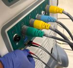
| + | *Colored plugs from splitter connect to St. Jude amplifier on main cart | ||
| + | [[File:NavX16.jpg|thumb|150px|left|Splitter cables]]<br style="clear:both" /> | ||
| + | *From top drawer of main cart remove patch connection unit | ||
| + | [[File:NavX17.jpg|thumb|150px|left|Patch unit]]<br style="clear:both" /> | ||
| + | *Secure patch unit over table control as shown | ||
| + | [[File:NavX18.jpg|thumb|150px|left|patch unit location]]<br style="clear:both" /> | ||
| + | *Patch unit plugs into amplifier here | ||
| + | [[File:NavX19.jpg|thumb|150px|left|Patch unit plug location]]<br style="clear:both" /> | ||
| + | *Locate power, ground, and fiber cables on side of main cart | ||
| + | [[File:NavX20.jpg|thumb|150px|left|Cables on side of main cart]]<br style="clear:both" /> | ||
| + | *Plug in power cord | ||
| + | [[File:NavX21.jpg|thumb|150px|left|Power cord]]<br style="clear:both" /> | ||
| + | *Clip ground to other ground cables or suitable metal object | ||
| + | [[File:NavX7.jpg|thumb|150px|left|Ground]]<br style="clear:both" /> | ||
| + | *One end of fiber optic cable is plugged into bottom fiber port below plugs from earlier step marked "Precision" | ||
| + | [[File:NavX22.jpg|thumb|150px|left|Fiber cable plug]]<br style="clear:both" /> | ||
| + | *Other end of fiber cable plugs into St. Jude amplifier port marked "Precision" | ||
| + | [[File:NavX23.jpg|thumb|150px|left|Precision amplifier port]]<br style="clear:both" /> | ||
| + | ===Secondary cart part 2=== | ||
| + | *Identify fiber cable on back of secondary cart | ||
| + | [[File:NavX24.jpg|thumb|150px|left|Fiber cable secondary cart]]<br style="clear:both" /> | ||
| + | *Plug this cable into fiber port on St. Jude amplifier | ||
| + | [[File:NavX25.jpg|thumb|150px|left|Fiber plug on amplifier]]<br style="clear:both" /> | ||
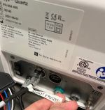
| + | *Identify black Ethernet cable near Maquette amplifier marked "Abbott Ensite" | ||
| + | *Plug into back of Quartz unit on secondary cart | ||
| + | [[File:NavX26.jpg|thumb|150px|left|Quartz unit Ethernet plug]]<br style="clear:both" /> | ||
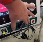
| + | *From front of ablator on secondary cart, identify quad cable | ||
| + | [[File:NavX27.jpg|thumb|150px|left|Ablator quad cable]]<br style="clear:both" /> | ||
| + | *Plug pins into A block 1-4 | ||
| + | [[File:NavX28.jpg|thumb|150px|left|Quad pins in C block]]<br style="clear:both" /> | ||
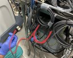
| + | *Identify large gray cable on back of secondary cart | ||
| + | [[File:NavX29.jpg|thumb|150px|left|Large secondary cart cable]]<br style="clear:both" /> | ||
| + | *Plug into port on St. Jude amplifier | ||
| + | [[File:NavX30.jpg|thumb|150px|left|St. Jude amplifier]]<br style="clear:both" /> | ||
Latest revision as of 17:19, 4 December 2023
Secondary cart
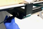
- Mount magnet to table plug side towards the foot of the table
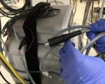
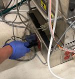
- Locate magnet cable on secondary cart and plug into magnet (arrows on plug will be toward the floor)
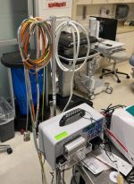
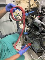
- Locate power, ground, and fiber optic cable hanging on secondary NavX cart
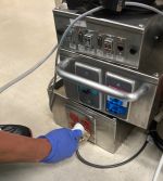
- Plug power cord into power outlet
- Ground, fiber, and data cables
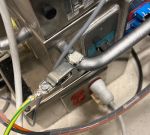
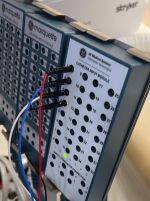
- Ground cable plugs into grounding block
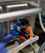
- Two Fiber optic cables connect as shown. Orange cables on top, gray under
- Serial data cable connects to left of fiber optic cables
Main Cart
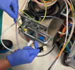
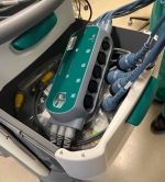
- From second drawer of main cart unpack splitter unit
- Splitter unit is installed between pin-blocks and amplifier, also between ecg cable and amplifier
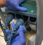
- Unplug A,B,C cables from amplifier
- Replace with A,B,C cables from splitter
- Repeat with ecg cable
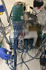
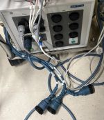
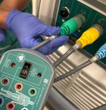
- A,B,C and ecg cables plug into splitter
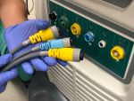
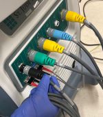
- Colored plugs from splitter connect to St. Jude amplifier on main cart
- From top drawer of main cart remove patch connection unit
- Secure patch unit over table control as shown
- Patch unit plugs into amplifier here
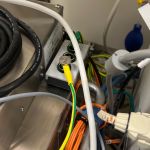
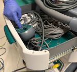
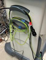
- Locate power, ground, and fiber cables on side of main cart
- Plug in power cord
- Clip ground to other ground cables or suitable metal object
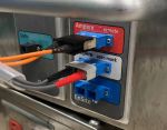
- One end of fiber optic cable is plugged into bottom fiber port below plugs from earlier step marked "Precision"
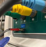
- Other end of fiber cable plugs into St. Jude amplifier port marked "Precision"
Secondary cart part 2
- Identify fiber cable on back of secondary cart
- Plug this cable into fiber port on St. Jude amplifier
- Identify black Ethernet cable near Maquette amplifier marked "Abbott Ensite"
- Plug into back of Quartz unit on secondary cart
- From front of ablator on secondary cart, identify quad cable
- Plug pins into A block 1-4
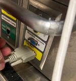
- Identify large gray cable on back of secondary cart
- Plug into port on St. Jude amplifier


